Articles
Flicka Improvements
Owner-built modifications, refits and upgrades — bowsprit rebuilds, canvas, joinery, plumbing.
-
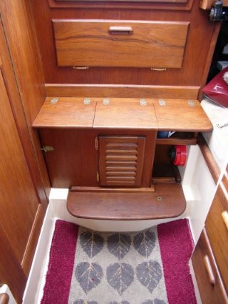
Companionway Box
Replacing the Flicka 20's factory companionway steps with a teak-faced ply storage box — including a louvred door for engine access.
By Angus Beare
-
Cockpit and Companionway Canvas — Ben Main Jr
Tom Davison on the cockpit dodger and companionway canvas he had made for Flicka Ben Main Jr (Pacific Seacraft hull #315).
By Tom Davison
-
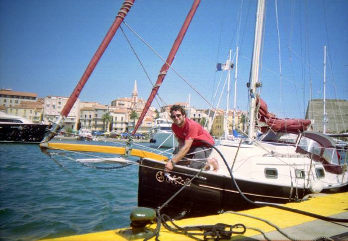
An Improved Bowsprit for a Flicka
Replacing the original Pacific Seacraft Douglas-fir bowsprit on Caraway with a longer custom Oregon-pine sprit — including a Fortress anchor mount and the bigger headsail slot it created.
By Angus Beare
-
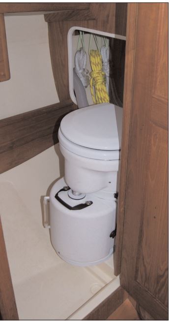
Installing an Air Head Composting Toilet in a Flicka PDF
The Dawsons document an Air Head composting head retrofit aboard Flicka NINA. (PDF)
By Ellen and David Dawson